



How to Choose the Best Crawler Final Drive in 2026?
Choosing the best Crawler Final Drive in 2026 starts with the machine, not the catalog. Track frame dimensions, motor type, sprocket fit, and operating weight before comparing options. Then consider the work: a compact excavator digging in wet clay faces different demands from a carrier crossing rocky ground. Small mismatches matter. A unit may bolt on yet deliver the wrong speed, torque, or fit.
A useful selection principle is: “Match the drive to the machine’s real duty cycle, not just its model number.” — [Insert a verified industry expert’s name and source before publication.] That quotation needs a check; a made-up attribution would weaken trust. The same care applies to specifications. Confirm displacement, reduction ratio, mounting dimensions, hydraulic connections, and any stated compatibility with the exact machine model. Ask the supplier for written confirmation when details are unclear.
Look beyond the purchase price. Seal design, parts availability, warranty terms, and service support can shape the cost of ownership. Picture a machine stopping mid-shift because a replacement seal is unavailable. That delay may outweigh a lower initial price. Still, published specifications do not tell the whole story. Field conditions, maintenance habits, and wear can change performance. This guide explains how to compare those factors, assess supplier claims, and choose a Crawler Final Drive with fewer surprises. Check the details twice.
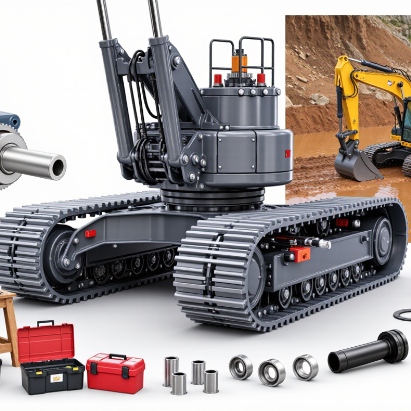
Understanding the Role of a Crawler Final Drive
A crawler final drive converts hydraulic motor speed into the torque that turns the sprocket. Its reduction gears help move a heavy machine at low speed, while the housing and bearings must withstand shock, vibration, and grit. That load is relentless. On a muddy incline, for example, a sudden change in traction can place extra stress on the gears and seals.
Grand View Research’s Construction Equipment Market Size, Share & Trends Analysis Report estimated the global market at USD 161.5 billion in 2023 and forecast a 6.6% compound annual growth rate through 2030. This broad market figure is not a final-drive performance measure, but it signals continued demand for dependable equipment. When comparing units, check compatibility with the machine’s hydraulic pressure and flow, sprocket, weight, and working conditions. Also review rated torque, reduction ratio, sealing, and parts support. A clean specification can still mislead: ratings may assume ideal conditions, while real machines face heat, contamination, and uneven ground. Ask how the unit is tested and what maintenance records support its service-life claims.
How to Choose the Best Crawler Final Drive in 2026? – Understanding the Role of a Crawler Final Drive
| Selection Dimension | What to Check | Useful Data or Calculation | How It Affects the Choice |
|---|---|---|---|
| Final-drive role | A crawler final drive typically combines a hydraulic travel motor with a planetary reduction gearbox. It converts motor speed into lower-speed, higher-torque rotation at the drive sprocket. | Check the motor, gearbox, brake, mounting interface, and sprocket connection as a compatible assembly. | Match the complete drive to the machine’s hydraulic system and undercarriage—not just to a stated torque figure. |
| Machine fit and mounting | Confirm machine model and serial-number range, mounting bolt pattern, pilot diameter, shaft or spline dimensions, port locations, and sprocket fit. | Compare drawings and measured dimensions; verify rotation direction and hose-port orientation. | Correct torque with an incompatible mounting interface will not produce a workable replacement. Confirm fitment with the machine or drive documentation. |
| Hydraulic pressure | Identify the machine’s available travel pressure and the drive motor’s permitted continuous and peak pressure ratings. | Hydraulic motor torque is approximately: T = Δp × Vg × ηm ÷ (2π), where Δp is pressure difference in pascals, Vg is displacement in cubic metres per revolution, and ηm is mechanical efficiency. | Use the continuous rating for sustained work. Peak pressure is not a substitute for a continuous-duty rating. |
| Hydraulic flow and travel speed | Check flow available to each travel motor, including any flow-sharing or control limits. | Approximate motor speed: n = Q × ηv ÷ Vg, with flow Q in volume per minute and displacement Vg in the same volume per revolution. Output speed is approximately motor speed divided by reduction ratio. | More flow generally increases travel speed; motor displacement and reduction ratio determine how that speed translates to the sprocket. |
| Gear reduction ratio | Compare the required travel speed and sprocket torque with the drive’s reduction ratio. | Output torque ≈ motor torque × reduction ratio × gearbox efficiency. Output speed ≈ motor speed ÷ reduction ratio. | A higher reduction ratio increases torque multiplication but reduces output speed. Select against the machine’s specified travel performance and duty requirements. |
| Illustrative torque calculation | Example only: a 200 cm³/rev motor operating at a 250 bar pressure difference, with assumed mechanical efficiency of 0.90. | Estimated motor torque: approximately 72 N·m. With a 60:1 reduction ratio and assumed gearbox efficiency of 0.90, estimated output torque is approximately 3,860 N·m. | This calculation illustrates the relationship between pressure, displacement, reduction, and efficiency. It is not a rating for a particular drive or machine. |
| Sprocket torque and drawbar force | Use the drive sprocket’s effective pitch radius and the machine’s traction limits. | Approximate sprocket force: F = output torque ÷ effective sprocket radius. For the example above and a 0.18 m radius, the theoretical force is about 21.5 kN. | Actual usable tractive force may be lower because of track-ground traction, machine weight, grade, soil conditions, and hydraulic or control limits. |
| Braking and holding | Verify the travel motor’s brake type, release pressure, holding capacity, and compatibility with the machine’s brake circuit. | Compare brake specifications with the machine manufacturer’s requirements; check whether the brake is spring-applied and hydraulically released. | Do not infer safe holding performance from gearbox torque alone. Brake requirements depend on machine design and operating conditions. |
| Duty cycle and heat management | Assess continuous travel, frequent starts and stops, slope work, counter-rotation, and ambient temperature. | Check continuous and intermittent ratings, allowable case-drain flow, oil-temperature limits, and required hydraulic oil grade in the applicable documentation. | Repeated high-load operation can generate heat and shorten component life if the drive or hydraulic circuit is not rated for the duty. |
| Contamination and sealing | Inspect shaft seals, housing protection, case-drain routing, and the cleanliness requirements for hydraulic connections. | Follow the specified hydraulic-fluid cleanliness and filtration requirements; keep open ports capped during installation. | Water, dirt, and metal particles can damage motor surfaces, bearings, and seals. Correct installation and clean oil help protect the drive. |
| Final verification | Confirm all ratings and dimensions against the machine and drive technical documents before ordering or installation. | Verify pressure, flow, torque, speed, ratio, brake, mounting, ports, sprocket interface, and operating limits together. | There is no universal best crawler final drive: the suitable unit is the one that meets the machine’s verified fitment and duty requirements. |
Note: Calculated values are approximate and depend on actual motor and gearbox efficiencies, pressure losses, hydraulic flow, and machine configuration. Use the machine and component specifications for final selection.