

How to Choose the Right ADSS Clamp for Your Project
Reliable aerial fiber depends on more than the cable itself. The Adss Clamp must hold the cable securely without exceeding its permitted load or damaging its outer sheath. The stakes are growing: the International Telecommunication Union’s Facts and Figures 2024 report estimates that 5.5 billion people use the internet. As networks extend into more communities, small hardware choices can affect long-term reliability.
Choosing a clamp starts with the cable manufacturer’s specifications. Check the cable’s outside diameter, recommended support method, allowable tension, and planned span. Then consider the route: pole spacing, wind exposure, possible ice loading, and changes in elevation can all influence the required holding force. IEEE 1222-2019 provides a technical framework for all-dielectric self-supporting (ADSS) optical fiber cables, but it does not replace project-specific cable and hardware guidance. Verify that the clamp manufacturer lists the exact cable range and intended installation conditions. A close-looking fit is not proof.
Small parts matter. An undersized clamp may compress the sheath; an oversized one may not grip reliably. Yet diameter alone is not enough. Review installation instructions, compatible fittings, and any specified torque or tension limits with the supplier or project engineer. Field conditions rarely match a tidy drawing perfectly, and that deserves a second look. Careful selection gives crews a practical starting point and helps keep the cable supported as conditions change.
Identify Span, Cable Diameter, and Rated Tensile Strength (RTS)
Span, cable diameter, and rated tensile strength (RTS) must be checked together. A longer span increases tension, but wind, ice, temperature, and sag limits also affect the load. Use the project’s NESC loading criteria and the cable manufacturer’s span-tension data; IEEE 1222 provides an industry reference for ADSS cable design and testing. Do not treat a clamp’s advertised span rating as universal. It depends on the cable and site conditions.
For example, a project worksheet might list a 250 m span, a 12 mm cable diameter, and 20 kN RTS. These are illustrative values, not standard design targets. Select a clamp specified for the cable’s actual diameter and compatible with the calculated support load. Check its published diameter range and rated holding capacity against the cable supplier’s requirements. A mismatch can crush the sheath or allow slippage.
Small mismatch. Big consequence.
Field crews should verify cable markings and measure the jacket before installation; nominal diameter can differ from the actual finished cable. Compare the design assumptions with local loading criteria and the IEEE 1222 cable specification, then confirm the clamp selection with the project engineer. One detail is easy to overlook: RTS describes cable strength, not a safe working load for every clamp. Apply the required design factors, and document any assumptions that remain uncertain.
Use IEC 60794-4-20 Cable Data to Establish Tension Requirements
How to Choose the Right ADSS Clamp for Your Project
Use IEC 60794-4-20 Cable Data to Establish Tension Requirements
Start with the cable’s IEC 60794-4-20 data sheet, not the clamp catalogue. The standard covers ADSS cables for aerial power-line installations, but it does not set one universal tension limit for every cable. Record the cable’s rated tensile strength, maximum installation tension, diameter, and mass per unit length. Check the project’s line-design report for span, wind, and ice assumptions. These inputs shape the load the clamp must transfer.
Keep the figures distinct. Rated tensile strength is not automatically a safe installation target. The maximum installation tension stated for the selected cable is the relevant limit during stringing; the final design load must also reflect route conditions and the engineer’s sag-tension calculations. IEEE 1222-2011 is another recognized ADSS cable standard to consult alongside the cable’s tested data. For example, if a hypothetical cable sheet gives a 20 kN rated tensile strength, do not treat 20 kN as the clamp’s required working load. It is only one input.
Then match the clamp’s approved diameter range and holding capacity to the calculated load, using the project’s specified safety criteria. A jacket that slips or becomes pinched can fail even when the clamp appears strong enough. Check the manufacturer’s test data for the exact cable construction, not just a similar diameter. Small difference. Recheck the assumptions when spans, ice exposure, or cable type change; I would question any selection based on a single tension number.
Match Clamp Diameter Range to the Cable’s Measured Outer Diameter
An ADSS clamp must match the cable’s measured outer diameter, not a nominal size copied from an old drawing. Measure the finished jacket with a caliper at several points along the cable, including more than one direction. This reveals ovality and small diameter changes. Record the largest and smallest readings. Keep the tool square to the cable, and avoid squeezing the jacket.
Use the measurements to check the clamp’s stated diameter range. For example, if readings fall between 12.3 and 12.6 mm, a clamp rated for 12–14 mm covers the measured cable; a 12.5–14 mm range may not. Do not force a borderline fit. IEEE Std 1222-2019 addresses ADSS cable requirements, while ITU-T G.652 specifies a fiber cladding diameter of 125.0 ± 0.7 μm. That figure describes the glass fiber, not the finished cable jacket—a distinction that is easy to overlook. Check the cable’s technical sheet and the clamp supplier’s range before installation. I would remeasure if readings sit close to either limit. Small detail. But it matters.
How to Choose the Right ADSS Clamp for Your Project — Match Clamp Diameter Range to the Cable’s Measured Outer Diameter
| Example Cable Section | Measured Cable Outer Diameter | Illustrative Measurement Variation | Suitable Clamp Diameter Range | Fit Assessment | Selection Check |
|---|---|---|---|---|---|
| Small-span distribution cable | 9.1 mm | 8.9–9.3 mm | 8–10 mm | Within range, with clearance for the measured variation. | Confirm the clamp’s stated range includes the cable’s full specified diameter tolerance. |
| Compact access cable | 10.8 mm | 10.6–11.0 mm | 10–12 mm | Within range and away from the upper limit. | Check that the gripping insert is intended for the cable construction and installation point. |
| Typical distribution cable | 12.6 mm | 12.3–12.9 mm | 12–14 mm | Within range; verify the actual cable tolerance against the clamp specification. | Do not select by nominal cable size alone; use the measured outside diameter. |
| Medium-diameter access cable | 14.7 mm | 14.4–15.0 mm | 14–16 mm | Within range, with the measurement comfortably inside the stated limits. | Verify that the clamp is suitable for the required span, tension, and support arrangement. |
| Large distribution cable | 16.5 mm | 16.2–16.8 mm | 16–18 mm | Within range; the complete tolerance band also fits in this example. | Check the clamp and cable installation instructions for the specified gripping method. |
| Large-diameter route cable | 18.4 mm | 18.1–18.7 mm | 18–20 mm | Within range, subject to confirmation of the cable’s maximum permitted diameter. | Confirm the selected clamp model’s approved cable range and mechanical rating. |
Note: The measurements and clamp ranges above are illustrative selection examples, not universal product specifications. Measure the cable’s outside diameter at several points using a suitable diameter gauge, account for the cable manufacturer’s stated tolerance, and select a clamp whose documented range covers the full expected diameter. Follow the clamp and cable manufacturers’ installation instructions; do not force an undersized clamp onto the cable.
Compare Clamp Holding Capacity with Maximum Installation Tension
How to Choose the Right ADSS Clamp for Your Project
Compare Clamp Holding Capacity with Maximum Installation Tension
An ADSS clamp must hold the cable securely without damaging its jacket. Check its rated holding capacity against the maximum installation tension specified for the cable and project. Do not treat these figures as interchangeable: installation tension describes the pulling load during stringing, while the clamp rating describes its ability to resist slipping under defined conditions. Numbers need context.
Confirm that the rating applies to the exact clamp type, cable diameter, and installation method. A dead-end clamp and a suspension clamp serve different roles. Also check whether the published capacity includes a safety factor, and follow the manufacturer’s installation instructions. A higher rating alone does not prove compatibility.
Field conditions matter. Long spans, changes in direction, wind, ice, and temperature can affect cable loads. Review the route design and ask the project engineer to confirm the required load margin rather than choosing by one number. During installation, use a suitable tension-measuring device and avoid sudden pulling loads. Inspect the cable jacket and clamp contact surfaces before tightening. Small detail. Big consequence. I have seen crews focus on the catalog rating and miss a mismatch in cable diameter. That is easy to overlook. Use verified project data, and record the selected clamp and installation tension for later inspection.
How to Choose the Right ADSS Clamp for Your Project
Compare the clamp’s rated holding capacity with the cable’s maximum installation tension. The example values below are illustrative only; confirm actual cable tensions and clamp ratings with the project design and supplier documentation.
How to read the chart: For each project case, the clamp’s rated holding capacity should meet the project’s specified requirements and exceed the maximum installation tension by the required design margin. Do not select a clamp from this illustrative comparison alone.
Check Wind, Ice, Temperature, and Sag Loads for the Project Span
How to Choose the Right ADSS Clamp for Your Project
Start with the actual span, not a catalogue estimate. Record pole spacing, cable diameter, installation tension, and expected sag. A clamp that fits the cable but cannot handle the tension is not a suitable choice. Small details matter.
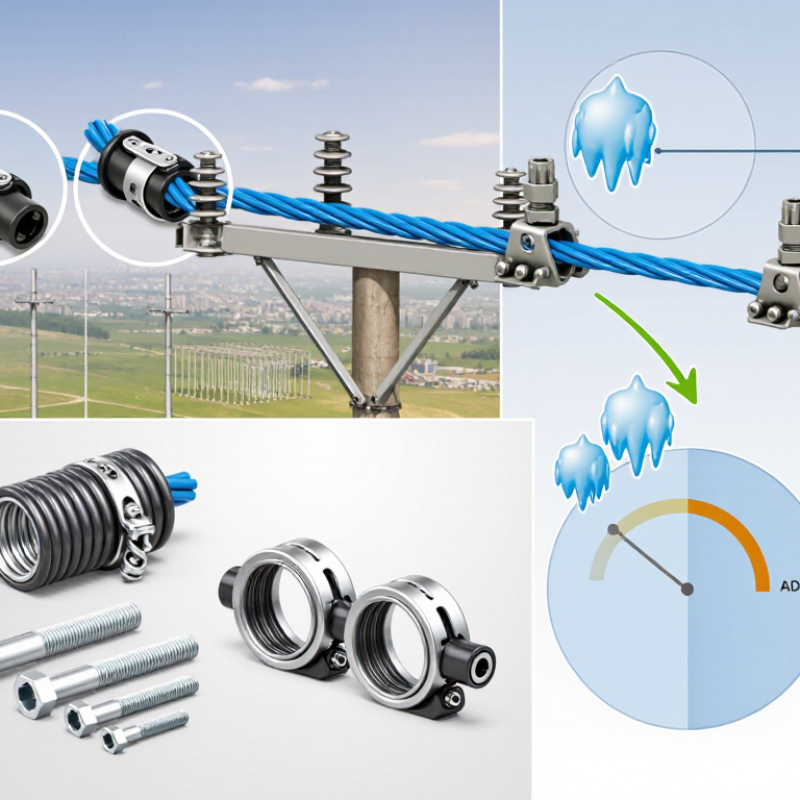
Wind can push the cable sideways and increase mechanical load on the support points. Ice adds weight and may change the cable’s effective diameter. Use project-specific wind and ice assumptions, including the possibility that both occur together. Do not rely on a mild-weather estimate. Check that the clamp’s rated holding capacity and contact surfaces match the cable design; excessive pressure can damage the sheath, while too little grip may allow movement.
Temperature changes also matter. Cable length and tension shift as conditions move from hot afternoons to cold nights. Calculate sag and tension for the relevant temperature range, then check the most demanding span and loading case. Follow the cable and clamp manufacturers’ published limits, and have a qualified designer verify the assumptions. It is easy to focus on the worst wind value and overlook temperature. That deserves a second look. Recheck measurements on site, since real spans rarely match a neat drawing exactly.
